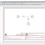
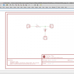
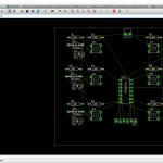
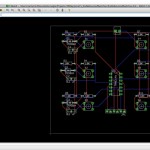
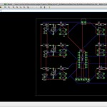
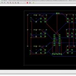
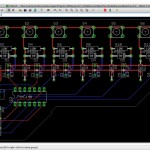
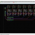
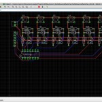
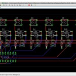
So switches, they’re easy. Two leads, and a pull up/down resistor depending. My requirements for this little board is that it be flexible as to what kind of data I’m going to feed a micro-controller (i.e. is
actuated 5V or 0V) and that it make an attempt at making this already ridiculously easy circuit that much faster to plug into a breadboard.
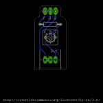
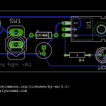
In this version a little tactile momentary button stands in for all switches. You could solder in this button, or solder in wire leads to a different switch. I don’t like this package design for this purpose, though. I’d like to electrically connect the leads on the board the way they are in the button so the two “extra” holes can be used for a second circuit. Next round.
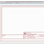
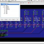
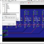
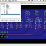
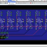
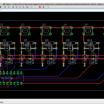
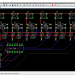
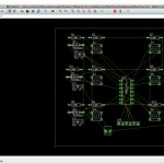
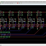
Boards A, B and E are 0.5 inches. Boards C and D are 0.6 in. The longest pcb is 1.5 inches long.
In Version A (left to right, btw) the headers are spaced such that P (for Pull) and I (for Input) can go into the rails of the breadboard, and D for data will reach a row (I measured the distance to be 9/32 inch to the first hole on an older Jameco Value Pro breadboard, we shall see). Since the switch is pretty big, I cut a hole in the board so extra lead lines can be connected to that row.
Version B is the same pin layout but the switch is swiveled off to hang off the side of the breadboard. A hole for a supportive standoff is at the far edge in case pressing the tact switch starts to lift the pcb out off the breadboard.
Version C has the assumtion that a jumper wire will be soldered into the pcb to connect to the Arduino, and that the standoff is helpful.
Version D, same as C, standoff discarded.
Version E, whole little unit with all the headers all in a row. Can use it across 3 rows, with lead wires, with a lead wire just on the data and headers on the P & I (it’ll eat up bus real estate)….
And the sad thing is – I could easily make 5 more… But not today! I’ll be at the JPL tweet-up when this posts in the morning and I need some sleep.
Goodnight!
